MC: Difference between revisions
SnakeTuning (talk | contribs) |
SnakeTuning (talk | contribs) No edit summary |
||
| Line 1: | Line 1: | ||
{{DISPLAYTITLE:SNAKE MAGIC CAP}} | {{DISPLAYTITLE:SNAKE MAGIC CAP}} | ||
[[File:MC_Device.jpg|left|thumb|500px|SNAKE MAGIC CAP]] | [[File:MC_Device.jpg|left|thumb|500px|SNAKE MAGIC CAP]] | ||
= Description = | |||
{{MC_Description}} | {{MC_Description}} | ||
<br clear=all> | <br clear=all> | ||
=Spark Modes= | |||
'''Sequential Mode'''.<br/> | '''Sequential Mode'''.<br/> | ||
This mode is used by almost all Honda OEM ECUs. Each coil fires once per cylinder. | This mode is used by almost all Honda OEM ECUs. Each coil fires once per cylinder. | ||
| Line 13: | Line 13: | ||
This mode is widely used by standalone sports ECUs. The two coils work as a pair. It is useful to clean the cylinders of fuel residue in the exhaust cycle if you are using "Running Rich" for your boosted setup. | This mode is widely used by standalone sports ECUs. The two coils work as a pair. It is useful to clean the cylinders of fuel residue in the exhaust cycle if you are using "Running Rich" for your boosted setup. | ||
=Installation= | |||
[[File:MC_Install_01.jpg|thumb|right|STEP 1: Aftermarket parts]] | [[File:MC_Install_01.jpg|thumb|right|STEP 1: Aftermarket parts]] | ||
'''STEP 1: Aftermarket parts''' | '''STEP 1: Aftermarket parts''' | ||
| Line 59: | Line 59: | ||
<br clear=all> | <br clear=all> | ||
=Self Diagnostic= | |||
[[File:MC_DTC_LED.jpg|thumb|right|Self Diagnostic LED]] | [[File:MC_DTC_LED.jpg|thumb|right|Self Diagnostic LED]] | ||
*Turn ignition ON | *Turn ignition ON | ||
| Line 84: | Line 84: | ||
|} | |} | ||
=Troubleshooting= | |||
{{Note|error|Some Chinese Distributors or re-manufactured one has a different shaft height than OEM. In a case if you got DTC 1, 2, 3 or 4 rotor height and it’s straight installation must be measured and adjusted.}} | {{Note|error|Some Chinese Distributors or re-manufactured one has a different shaft height than OEM. In a case if you got DTC 1, 2, 3 or 4 rotor height and it’s straight installation must be measured and adjusted.}} | ||
'''3 point measurement procedure using a caliper''' | '''3 point measurement procedure using a caliper''' | ||
Latest revision as of 21:06, 8 January 2026

Description
The world's first dual mode COP solution for upgrade your Honda/Acura OEM distributor.
Direct replacement for OEM parts, no modification required.
Spark Modes
Sequential Mode.
This mode is used by almost all Honda OEM ECUs. Each coil fires once per cylinder.
Increased mileage and durability of coils. Keeps the Coils Cooler.
Wasted Spark Mode.
This mode is widely used by standalone sports ECUs. The two coils work as a pair. It is useful to clean the cylinders of fuel residue in the exhaust cycle if you are using "Running Rich" for your boosted setup.
Installation

STEP 1: Aftermarket parts
- SNAKE Distributor Cap replacement with built-in COP unit
- SNAKE Ignitor Unit replacement
- SNAKE Rotor replacement

STEP 2: Remove OEM parts from the Distributor
- OEM Coil
- OEM Ignitor unit
- OEM Rotor

STEP 3: Install SNAKE Ignitor Unit
- Install SNAKE Ignitor unit to the distributor
- Connect 3 internal distributor wires to the ignitor unit as shown

STEP 4: Insulate +12V Power Wire
- Use 5mm (0.2 in) heatshrink tube to insulate the wire with the ring terminal.

STEP 5: Install SNAKE Rotor
- Use SNAKE rotor and OEM rotor Bolt.

STEP 6: Set distributor type
- Connect the white plug to the properly socket
- Type A: H22, H23, F20, F22, F23 Engines.
- Type C: B16, B18, B20, D15, D16 Engines.

STEP 7: Install Distributor Cap
- Connect 4 pin connector from the Ignitor unit to the Cap.
- Install Cap to the Distributor housing.
Self Diagnostic

- Turn ignition ON
- Crank the car at least 3 seconds
- Check DTC(s) on the Self diagnostic LED
| Code | Description |
|---|---|
| 0 | Solid LED. NO ERRORS Detected |
| 1 | No signal from A hall sensor |
| 2 | No signal from B hall sensor |
| 3 | No signal from C hall sensor |
| 4 | No signal from D hall sensor |
| 5 | No rotor installed |
| 6 | No signal ICM (ECU Fault) |
Troubleshooting
3 point measurement procedure using a caliper
- Measure rotor height, as shown on a pictures below in a 3 points. Center of the rotor and both ends of it.
- Carefully check the parallelism of the rotor shaft and caliper to get the most accurate height measurement.
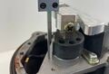
Point 1. Center
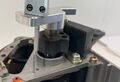
Point 2. First end
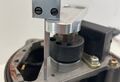
Point 3. Second end


Check your measurements
- All three measurements must be the same in a 0.2 mm (0.008 in) range. If one of three points is lower or higher than other its meaning not straight rotor installation. You need loosened center bolt and fix rotor straight. Then re measure.
- Rotor height in a center point must be in a range from 42.0 mm (1.653 in) to 42.6mm (1.677 in). If rotor height is out of range you need adjust distributor shaft, Hit a little above or below the shaft using hammer and re-measure center point.